User Tools
Table of Contents
Get started with 2D Cam
Welcome to this step-by-step introduction of MicroTech StellaData 2D Cam. The point of the introduction is not to teach you the software in detail, but rather get you going as soon as possible with the software and show you the basics. We've chosen a very simple detail for the task. We will show you the whole process from drawing the detail to create the NC program.
The part is drawn in millimeters. You can obviously translate this to inch if you so wish.
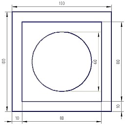
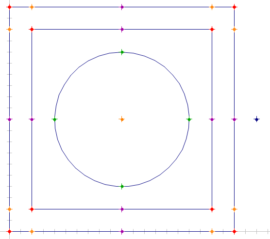
The part we are going to make looks like this:
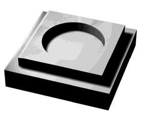
A drawing of the detail.
Design
Lets get started! Follow the steps below:
- Start 2D Cam
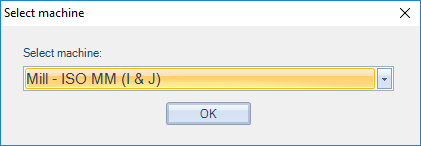
- Select a milling machine, e.g. Mill - I & J
- Now 2D Cam have started.
Step 1
We will start with drawing the square of 100 x 100
- Click on the line tab
- Click on the Line 2 points function
- Click on Values… in the lower right corner of the screen
- For the first point, enter X0 Y0. To jump to the next field, use Enter or Tab.
- Click on Values… again.
- For the second point, enter X100 Y0
If the linje we have created, ends up outside of the screen you may use the function Zoom fit
Repeat the steps above, but with these values:
- For the first point, enter X100 Y0
- For the second point, enter X100 Y100
- For the first point, enter X100 Y100
- For the second point, enter X0 Y100
- For the first point, enter X0 Y100
- For the second point, enter X0 Y0
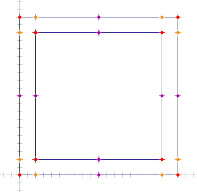
At this point it should look something like this:
If the square is too small you may zoom in on it. Either using the mouse-wheel, or the Zoom fit function (Hotkey N)
Step 2
Now let's draw the inner square. You can do it the same way as in the previous step, or like we are going to do now with the Rectangle function.
Let's move on with drawing the rectangle of 80 x 80
- Click on the line tab
- Click on the Rectangle 2 points function
- Click on Values… in the lower right corner of the screen
- For the first point, enter X10 Y10. To jump to the next field, use Enter or Tab.
- For the second point, enter X90 Y90
At this point it should look something like this:
If you accidently made an error in any of the previous steps you may Undo the last thing you did with the Undo function (Hotkey Ctrl-Z)
Step 3
Now let's draw the circle with diameter 60
- Click on the Circle tab
- Click on the Circle with diameter
- Click on Values… in the lower right corner of the screen
- For the center-point, enter X50 Y50
- Enter 60 in diameter value box
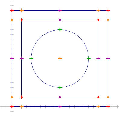
At this point it should look something like this:
And we are done with the drawing. Next steps is to create some NC-code.
Tool paths
Points
To be able to place our tool-path we need to make sure we display all the auto points. Fastest way to do this is to enable the points in the lower-right corner of the screen.
We are going to make it easy for us and just enable all the points, e.i. LL, LC, CC, MP, EP, CP, QP should be lit up.
Let's draw a starting point for our tool-path. This may just be sketched, but for this introduction we'll draw a proper point.
- Click on the Point tab
- Click on the Point with coordinates function
- Click on Values… in the lower right corner of the screen
- For the point, enter X110 Y50
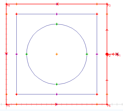
At this point it should look something like this:
Outer square
Now we're going to create NC-code around the outer square. Do like this:
- Click on the NC data tab
- Click on the point that we drew as our start-point (X110 Y50). The point should be marked Red and if you move the mouse, a red line will follow the mouse pointer.
If you happend to select the wrong point you may use the Undo last NC function (Hotkey Å)
We have just made a rapid-feed to X110 Y50. Let's continue:
- Click on mid-point (Magenta) on the horizontal line that makes up an edge of the square.
- Click on the upper End-point (Red) on the same line.
- Click on the upper-left End-point (Red) on the vertical line.
Continue around the square until you get to the mid-point where we started.
Remeber that if you made an error somewhere you may use the Undo last NC function (Hotkey Å)
At this point it should look something like this:
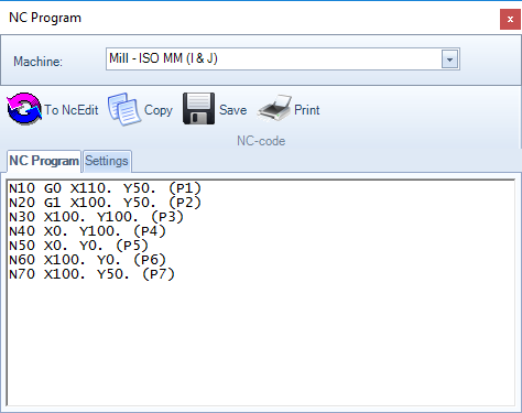
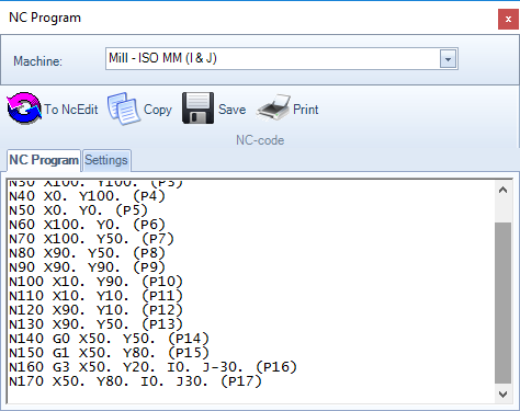
To look at the NC-code, do like this:
- Click on the NC data tab
- Click on the Show NC-code function
At this point it should look something like this:
Inner square
Let's continue to create tool-paths around the inner square.
We already are at a good starting point for our tool-path so we just continue as with the last square.
- Click on the NC data tab
- Click on mid-point (Magenta) on the horizontal line that makes up an edge of the square.
- Click on the upper End-point (Red) on the same line.
- Click on the upper-left End-point (Red) on the vertical line.
Continue around the square until you get to the mid-point where we started.
Nu ska det se ut ungefär så här på skärmen:
At this point it should look something like this:
The circle
Now all we have left to do is the circle. Do like this:
First let's move with parid to the center of the circle:
- Click on the NC data tab
- Click on the Center-point (Orange) of the circle (X50 Y50)
- Click on any of the Quadrant-points of the circle (Green) of the circle. (E.g. X50 Y80)
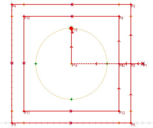
At this point it should look something like this:
- Click on the opposite Quadrant-point (Green) of the circle (E.g. X50 Y20)
- Select a direction of the arc by moving the mouse-pointer either to the left or right of the center-point.
- Click to confirm the direction.
- Repeat the steps above to complete the circular movement back to the start-point.
At this point it should look something like this:
And to look at the NC-code, do like before:
- Click on the NC data tab
- Click on the Show NC-code function
At this point it should look something like this:
This is the end of the introduction.

